
This guide walks engineers and architects through the decisions behind a thermally broken steel connection, from choosing a material to detailing the bolts. It is general guidance; the engineer of record is responsible for the final connection design.
1. Identify the Thermal Bridges
Start from the envelope drawings and list every place steel or concrete crosses the insulation line: canopy and balcony beams, shelf angles, rooftop dunnage and posts, parapet outriggers, column bases outside the envelope and cladding supports. Rank them by length or quantity; continuous elements such as shelf angles and repeated elements such as dunnage posts usually matter most.
2. Choose the Material
| Connection | Recommended material |
|---|---|
| Moment connections (balconies, canopies, cantilevers) | STB-1 |
| High-load shear and bearing connections | STB-1 |
| Shelf angles, dunnage posts, structural column bases | STB-1 |
| Light non-moment supports, isolation blocks | TBF (grade by bearing pressure) |
| Cold storage and freezer foundation isolation | TBF |
3. Set the Pad Thickness
Pad thickness is a trade-off. A thicker pad reduces heat flow, but it lengthens the bolt grip and makes the connection more flexible. Most connections land between 1/2″ and 1″ of STB-1; 2″ is used where the energy model demands it and the bolts are designed for it. Keep end plates no larger than the connection requires, since oversized plates add contact area and reduce the benefit of the break.
4. Check the Bolts
- Bending: with a thick pad in the grip, bolts in shear act partly in bending. Check combined shear, tension and bending.
- Prying: check end plate thickness and prying action for the tension bolts in moment connections.
- Grip length: specify bolt lengths that account for the pad, washers and bushings.
- Slip-critical joints: a thermal break plate in the grip changes the faying surfaces and can affect clamping force over time. Confirm the treatment of fillers and non-steel plies under the governing steel design standard before designing a thermally broken joint as slip-critical.
5. Isolate the Bolts
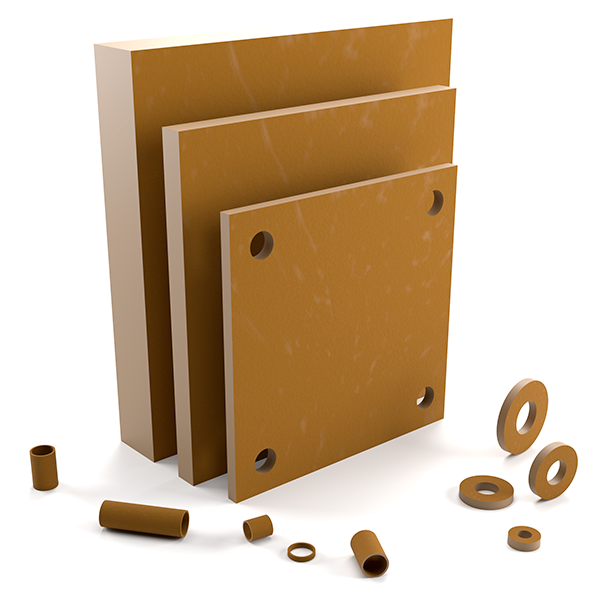
Use thermal break washers and bushings on the exterior side of each bolted connection so the bolts do not carry heat around the pad. Size bushings to the bolt and hole diameter and the exterior plate thickness.
6. Long-Term Load, Fire and Durability
- Creep: use a thermoset composite such as STB-1 for connections under sustained dead load.
- Fire: STB-1 is rated ASTM E84 Class A and Euroclass B. Confirm fire requirements for the connection location.
- Temperature range: STB-1 operates from -20 °F to +250 °F; TBF from -328 °F to +176 °F.
- Moisture: detail flashing so water drains away from the connection.
7. Detailing Checklist
- Pad size, thickness and hole pattern shown on drawings
- Bolt grade, diameter and length including pad, washers and bushings
- Washer and bushing locations called out
- Air/vapour barrier and insulation continuity around the connection
- Specification section referencing material performance (see our guide specification)
- Shop drawings coordinated with the thermal break fabricator
Request a Quote or Data Sheet
Send us your connection drawings, bolt schedule or load requirements and we will quote STB-1, TBF, washers and bushings cut and machined to your specification. Data sheets and design support are available for engineers and architects.
Call 800-580-4195 or use the form below. STB-1 typically ships in 5–7 days; TBF in as little as 3 days.